Description
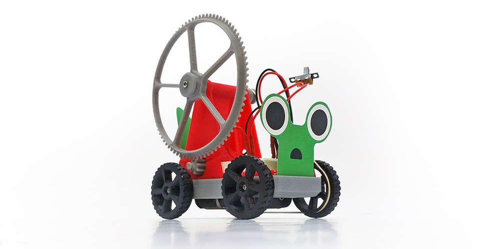
Use 3D printed parts, basic electronic components, and step-by-step instructions to build your own GearBug. Adapt your GearBug for fun challenges including drag races, hill climbs, or just plain cool looks!
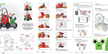
***see GearBug_Assembly_Instructions-Explore_Making.pdf in Files
The GearBug is designed using SolidWorks. Many advanced design techniques were used to design the part, but one key technique that is important for the designs functionality is sliding-fit parts (the axles that must slide in the axle shafts). To design these parts we left a 1mm gap between the axle and the axle shafts. The axles are 7mm in diameter and the axle shafts are 8mm in diameter.
Overview & Background
We created a fun and engaging vehicle after searching for an introductory project with broad appeal. The initial GearBug is easy to assemble but also provides opportunities for math and physics lessons as well as design challenges.
Objectives
- Follow instructions to create a functional GearBug
- Demonstrate understanding of an electrical circuit to power the GearBug
- Adapt the GearBug for challenges of speed and hills
- Comprehend the relationship between gear ratios and speed/power
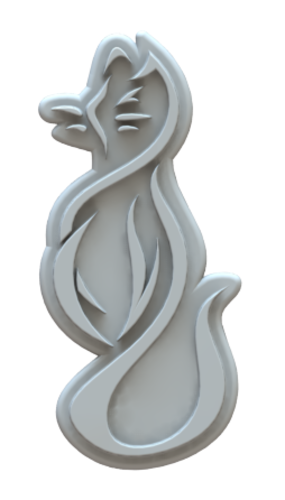
- Design a cover to change the appearance of GearBug
Audiences
grade 3 to adult
Subjects
Electronics, Physics, Math, Design, Art
Skills Learned (Standards)
- Understand the wiring requirements and completion of circuit
- Document the process of creating GearBug and any alterations done
- See the relationship between gear ratios and speed/power
Lesson/Activity
Students can work in groups of 2 or 3, promoting teamwork and reducing material costs. If teams used, we recommend having the students switch roles every 5 to 10 minutes so all students assemble, read, and document. One suggestion for homework is the documentation of their process.
We've worked hard to create a step by step assembly guide and resources. Please also see Resources section and Thing files.
You can extend the lessons by including challenges for the GearBug (what gear ratio is fastest, most powerful?). For more advanced groups, students can calculate the speed based on gear ratios and/or design new gears for GearBug. For art classes, students can create shells or other fun additions to give their GearBug different characteristics.
Duration
One hour is sufficient for basic activity. The extensions can take 30 minutes to several hours depending on the depth and number of extensions added.
Materials:
Rubric/Assessment
Students could be assessed on the following:
- Documentation of the process
- Completed GearBug that can race others
- Understanding of the relationship between gear size and speed/power
Handouts and Assets
More from this category
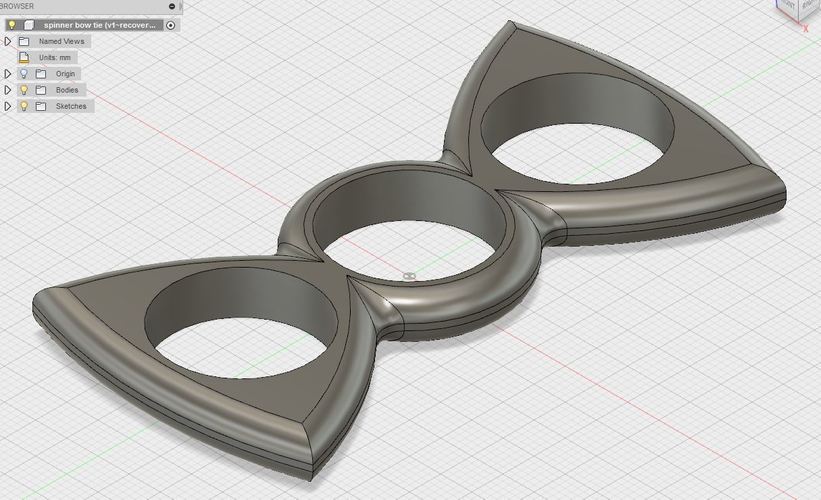
Fidget spinner bow tie style
by 3deyedoc
I had a request for a bow tie shaped spinner and this was the result. I was able to print this on...
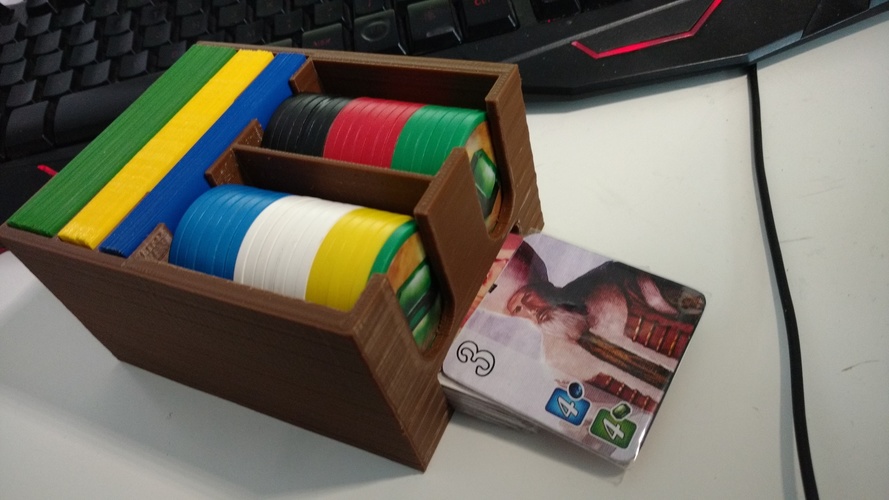
ORGANIZ3D tm Splendor Full Box
The Splendor Full Box From the ORGANIZ3D tm Brand, created by HOCHEFAB 3D / Crazy-Games. The pic...
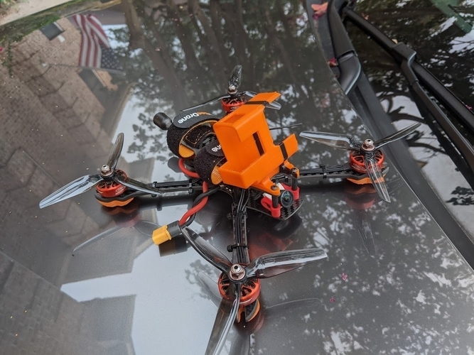
Strix Screech Hero 8, 20॰ Mount
by Br8knitOFF
TPU, 80% infill, color of your choice.

Dubai Call Girls Service 0525382202 Indian Call Girls in Dubai
by voyal73886
Dubai Call Girls Service 0525382202 Ind
Comments (3)
Sign in to leave a comment.
Introduction to electronics is a captivating journey into the world of circuits and components that power our modern technology. It encompasses the study of electrical circuits, semiconductors, and electronic systems. Aspiring electronics enthusiasts can delve into the fundamentals of voltage, current, and resistance, gaining insights into the intricate interplay of electrons. To enhance learning, resources like the <a href="https://www.nextpcb.com/free-online-gerber-viewer.html">free online Gerber Viewer</a> offer a practical dimension by allowing users to visualize printed circuit board (PCB) designs. This tool facilitates a deeper understanding of electronic lay
Здравствуйте! Наверное у Вас ошибка в установке ремней на шкивах. Не возможно одновременно установить 2 ремня на шкиву большого зубчатого колеса и на шкиву малого зубчатого колеса (который идет от моторчика), т.к. эти колеса вращаются в разные стороны!