
Description
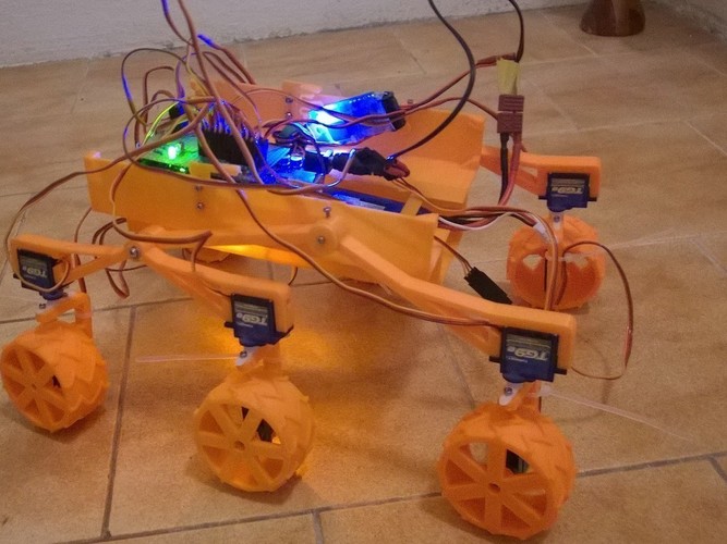
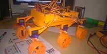
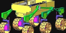
SummaryRC vehicle inspired by Mars rover Curiosity. Parts are printed on 3D printed. Main Processing Unit is Ardunio Mega. For moving used 6 9g servos with metal gear and edited for 360 rotating, for steering used 6 standart 9g servos.
Control is standard 4 channels. Power by 2S or 3S lipo battery - 6V SBEC.
------ Rover Mk II ----
https://www.youtube.com/watch?v=puso_W5l1AA
must see!
youtube:
0- presentation control https://www.youtube.com/watch?v=wAg5VBJ3dfA
1- https://www.youtube.com/watch?v=4kdi7T4iqAI
2 - https://www.youtube.com/watch?v=Wh_syhhbGSI
simple instruction: http://www.mochr.cz/index.php?id=rc-rover ( wait for complete...)
WARNING
new homepage:
http://www.mochr.cz/index.php?id=rc-rover InstructionsArduino files are in the RAR archive.
BOM
6x 9g servo (TG9e, TowerPro SG90)
6x 9g servo with metal gear (TGY-5009M)
Arduino Mega 2560
SBEC Lipo 5/6V 5/6A for 3S lipol
3S Li-pol about 1300mAh
12x servo extension cable (10-30cm)
12x resitor 2.2K ohm
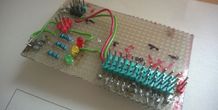
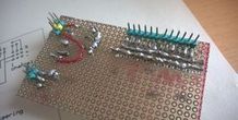
universal PCB
green LED 3mm
red LED 3mm
yellow LED 3mm
3x resistor 160 Ohm
some pins
42x screw M2x6
6x screw M2.5x6
2x screw M3x25
8x screw M3x6
8x nut M3
4x nut M2
4x white LED 5mm
4x red LED 5mm
RC TX and RX
connector to Arduino
cable ties
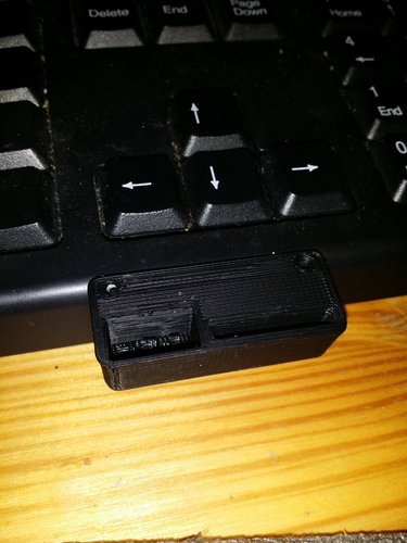
3D printed parts
Arduino setup
After build Rover is needed to center the servos.
Upload this file to Arduino.
// 2 - 7 for all steering servos
// 8 - 13 for all wheels servos
int pin = 13;
check all servos with serial monitor for center position. My value is about 1300-1500. Value write to this file , and upload to Arduino.
// Data from calibration servos - center position of servo
int W1_center = 1350;
int W2_center = 1390;
int W3_center = 1360;
int W4_center = 1370;
int W5_center = 1435;
int W6_center = 1355;
int S1_center = 1500;
int S2_center = 1480;
int S3_center = 1420;
int S4_center = 1410;
int S5_center = 1480;
int S6_center = 1480;
Now you need center signal from RC. Connect RX to PCB and Arduino connect with PC. Control stick on TX set to neutral. Serial monitor write some values. Copy this values to Excel and make average value ( about 50 values is OK). Repeat to second channel.
// calibration RX signal
Serial.println( value_ch1);
and
// calibration RX signal
Serial.println( value_ch2);
Servo modifying
Servo with metal gear use to wheel. You must modifying to countinous rotating. Cut of potentiometer, add 2 resitors, cut of pin on tooth wheel.
instruction for example: https://learn.adafruit.com/modifying-servos-for-continuous-rotation/overview
More from this category
SD Card Flash Drive Holder
by Gpasteve
SD Card/ Flash drive holder that can be mounted to a 3d printer, a desk or a shelf .
0 ❤️
1 💬
0 ⬇️
$0.5
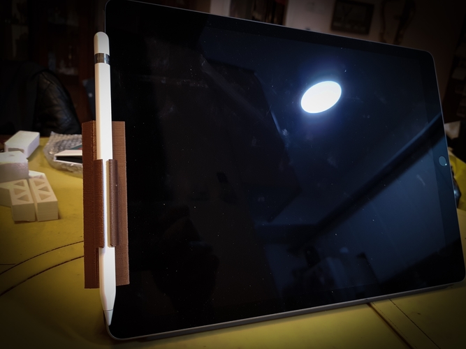
Apple Pencil with Smart Cover clips for iPad Pro
by vova_chmarak
Clips for iPad Pro with Smart Cover and apple pencil
1 ❤️
1 💬
0 ⬇️
Free
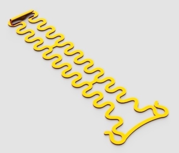
Flexible covid ear saver (13 to 24 cm long)
by imakina
Flexible ear saver 13 to 23 cm long. Only 1 gram each piece.
1 ❤️
1 💬
0 ⬇️
Free
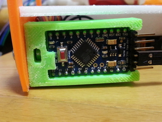
Arduino Pro Mini Holder
by dTom
SummaryUpdate V3, More secure to hold the Pro mini For Plotclock on Note 2 (http://www.thingivers...
5 ❤️
2 💬
2 ⬇️
Free
Aluhotend fan duct
by misan
SummaryFor a 25mm fan. Tap the the holes with M3 and use M3x16mm screws to fix the fan. Press th...
0 ❤️
1 💬
0 ⬇️
Free
Comments (1)
Sign in to leave a comment.
No comments yet. Be the first to comment!