Description
Summary
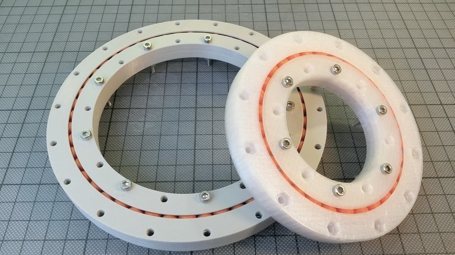
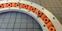
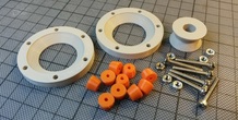
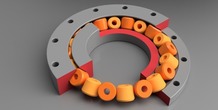
Ball-bearings are very popular for 3d-printing. However they often fail for real applications. Using Fusion 360 I've created a parametric design of a "Crossed Roller Slew Bearing". The result is a pretty accurate and robust bearing. The bearing including the rollers is 3d-printed in separate parts. There are a few screws needed to clamp the two halves of the inner race together.
The design process is really straightforward, so I've created a video tutorial how to design this slew bearing in Fusion 360. With some practice, such a bearing can be designed from scratch in less than 20 minutes. For students interested in 3d-Design, I recommend to install Fusion 360 and walk through the tutorial.
https://youtu.be/5o4Fj8OxkB8
The 3d-files available for downloading are a large version with 48 rolls, and a small version with only 10 rolls (top and bottom halves of the race are actually symmetrical, but for completeness both are available as STL).
If you need a bearing with other dimensions, the CAD-files of Fusion 360 are available for download. There are actually two different designs: a basic version with cylindrical rollers, and a more sophisticated version with conic rollers. The CAD-files are also available here:
http://a360.co/2r9MFf5
http://a360.co/2r9JnZf
Print Settings
Printer Brand:
Ultimaker Printer:
Ultimaker 2 Rafts:
No Supports:
No Resolution:
0.15 Infill:
35%
Standards
NGSS
Overview and Background
Lesson Plan and Activity
Install Fusion 360
Repeat the steps demonstrated in the video tutorial
Print and test the own design
Materials Needed
A 3d-Printer
Some Bolts and Nuts
Duration of Lesson
1-2 hours + time for 3d-printing
More from this category
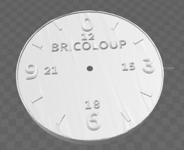
Horloge 24 h Bricoloup
Summary Petite Horloge de 200/200 fichier stl corriger 0/24h
1 ❤️
1 💬
0 ⬇️
Free
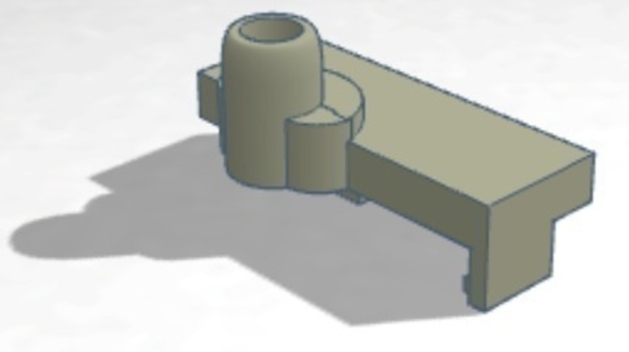
Palette PTFE Tube Holder MK2S
by malcinator
Summary This thing was made with Tinkercad. Edit it online https://www.tinkercad.com/things/48rs9...
1 ❤️
1 💬
0 ⬇️
Free
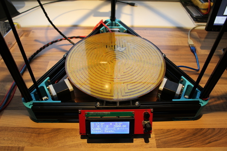
Kossel XL buildplate tabs (250mm glass)
by Oeve
Summary Made these mounts so was able to place a heat reflector under need the heated build plate...
1 ❤️
1 💬
0 ⬇️
Free
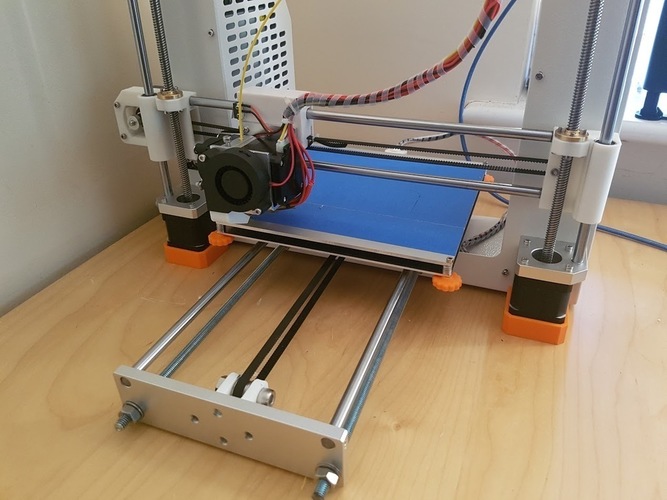
JG Aurora A3 Stable Feet
by CdRsKuLL
Summary A very simple mod to try and improve the print quality of the JG Aurora by making it more...
1 ❤️
2 💬
0 ⬇️
Free
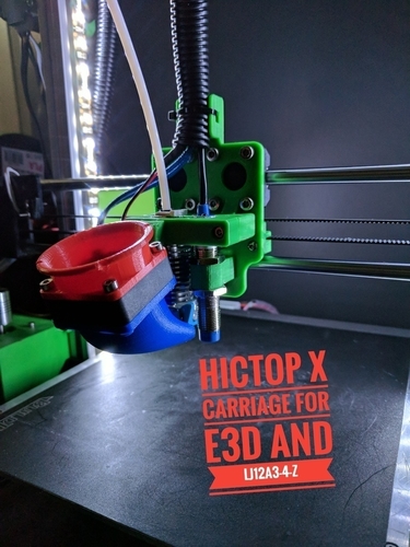
Hictop Prusa i3 X_Carriage mk3 for E3Dv6 LJ12A3
Summary New X carriage version, to support a LJ12A3-4-Z/BX sensor. This moves the sensor 17mm aw...
1 ❤️
2 💬
0 ⬇️
Free
Comments (1)
Sign in to leave a comment.
No comments yet. Be the first to comment!