Description
DESIGN PROCESS
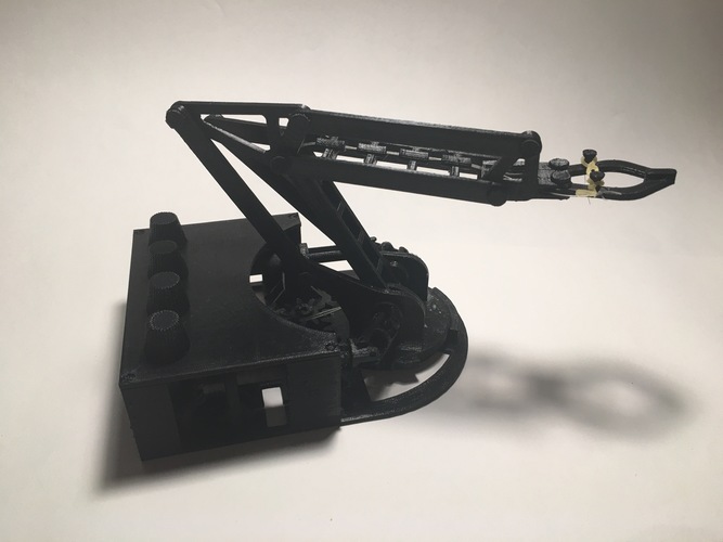
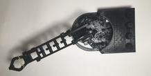
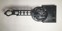
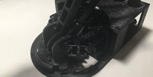
I have always been intrigued by robot arms and the different mechanisms that allow them to work. I really wanted to pursue the challenge of designing a small, desktop sized robot arm that could be controlled without servos or stepper motors.
After researching various types of robot arms, I discovered that all of them were utilizing servos or motors in the arm themselves. Basically, I found that to build a robot arm you needed some of the motors housed in the base of the arm that will rotate. My vision when I first started to design the arm, was a small 3D printed arm with a number of knobs on the base that would control it. No servos, no stepper motors, no electricity. I really wanted to test the limits of 3D printing and my mechanical knowledge to design a functional, fully mechanical desktop arm.
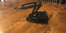
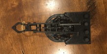
The biggest challenge was designing the base of the arm that would allow the knobs to turn parts of the arm that would rotate with the base of the robot as it turned. Initially I thought I would be able to get away with only using universal joints for this, but I soon found out this wouldn't work alone, because as the base rotates the connection would move further or closer to the base. I ended up using telescoping tubes with a cross intersection that would allow the axle to rotate, change lengths, and change direction. I went through a number of iterations to design universal joints that would work with my design. My final design allows each joint to bend up to 64 degrees while still transmitting the rotation.
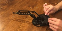
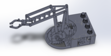
This project was designed in SolidWorks, and I am very happy with how it turned out. I learned a lot along the way, and I will be going forth and making future improvements to my design. I have since added some bike wax lubricant to the joints and it moves a lot smoother now. It can pickup and move small objects around, success!
You can see a video of it in action here!
SETTINGS
Machine: Makerbot Replicator z18
Material: PLA
Layer Height: 0.2 mm
Infill: 50 %
Support: No support up to 2 mm
Rafts: Yes
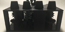
PRINTING
Print the following parts, in the correct orientation, and correct amount. Note some of the parts are printed horizontally to increase strength.
lower_base x1 - flat
spur_gear_18_9 x3 - flat
spur_gear_24_12 x1 - flat
spur_gear_60_30 x1 - flat
bevel_gear_20_15_gear1 x2 - flat
bevel_gear_20_15_gear2 x2 - flat
U_joint1 x2 - lying horizontally with the opening facing up and holes parallel to floor
U_joint2 x2 - lying horizontally with the opening facing up and holes parallel to floor
U_joint3 x2 - lying horizontally with the opening facing up and holes parallel to floor
U_joint_cross x4 - flat
telescoping_tube1 x2 - vertically
right_arm_ext1 x3 - flat
right_arm_ext2 x1 - flat
right_arm_ext3 x31 - flat
left_arm_ext1 x1 - flat
left_arm_ext3 x1 - flat
pin x12 - horizontally
pin2 x1 - horizontally
arm_ext_spacer x1 - horizontally
fishing_wire_spool x1 - flat
gripper1 x1 - flat
claw1 x1 - flat
claw2 x1 - flat
top_base x1 - flat
knob1 x1 - lying horizontally, rod is parallel to floor
knob2 x1 - lying horizontally, rod is parallel to floor
knob3 x1 - lying horizontally, rod is parallel to floor
knob4 x1 - lying horizontally, rod is parallel to floor
ASSEMBLY INSTRUCTIONS
Please watch the assembly video here for detailed instructions on how to assemble the arm.
Thanks for checking it out!
More from this category
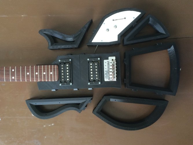
Electric Guitar
by imprende
I designed this Electric Guitar body to be printed on an Ultimaker 2 and be assembled without the...
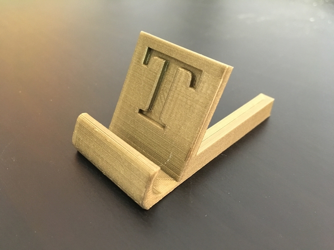
Iphone Stand
very easy to print !!!! G model but any other character available on demand !!!!! 3D PRINTIN...
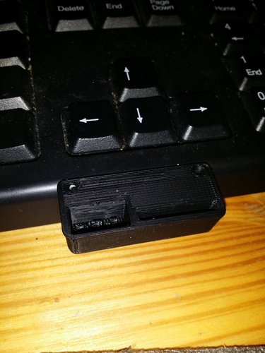
SD Card Flash Drive Holder
by Gpasteve
SD Card/ Flash drive holder that can be mounted to a 3d printer, a desk or a shelf .
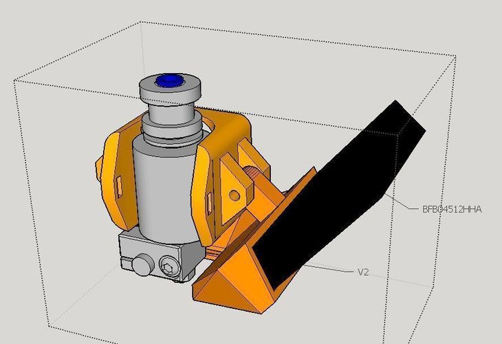
E3D V6 bowden Fan duct for Kossel
by dTom
Summary2 vents blow to hotendInstructionsbowden Fan : 45x12 ( Model : BFB04512HHA ) Layer high : ...
Apple Pencil with Smart Cover clips for iPad Pro
by vova_chmarak
Clips for iPad Pro with Smart Cover and apple pencil
Flexible covid ear saver (13 to 24 cm long)
by imakina
Flexible ear saver 13 to 23 cm long. Only 1 gram each piece.
Comments (6)
Sign in to leave a comment.
Thank you nwayland ! I have been printing and building the MeArm and EEZYbotArm, but looking for a purely mechanical design with no electronics, and this is it. Having great fun importing your STLs into FreeCAD and assembling your design in CAD to familiarize myself, will start printing parts soon. Had to cut the base plate into two pieces in Meshmixer, my little MP Select Mini is limited to 120mm cubed. Again, great design work, especially the telescoping tubes and U-joints !
Thanks rich942, glad you found my design!
Russell Francis, I'm sorry you had trouble with the assembly as the instruction video took longer than I expected to edit and complete; however, you can now refer to a link in the description for a detailed instructional video. Refering to your struggles with the printing, if you followed my print instructions and settings, the parts should come out with a fairly normal amount of supports in my opinion. If you need any more help with assembly or printing, feel free to ask me! I currently don't have my own 3D printer but I hope to get one soon, and I will make future improvements to my design if more people struggle with the assembly.
Thanks MakeShift, I thought your Outboard was awesome! I really liked your design of the motor and the housing, pretty cool.
nwayland, he said similar things about many of the entries in the mechanical design contest. I won't point out his entry, but I think he just realized it is not a popularity contest. Also I love this design! The way you solved the rotation problem was ingenious imho. I respect out of the box thinking like that.