Description
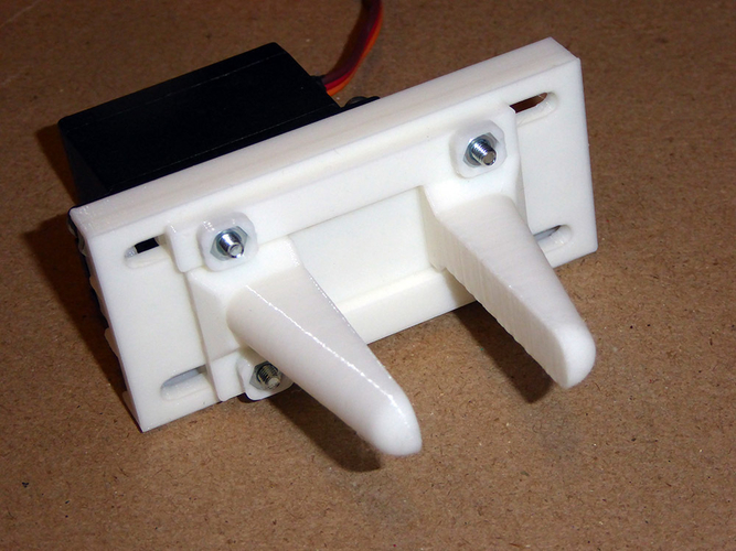
3D Printed Servo Controlled Robotic Gripper using rack & pinion drive for parallel jaw movement
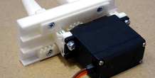
This is a robotic gripper/jaw that uses a low cost Tower Pro MG996R servo.
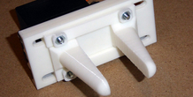
As opposed to some grippers that use a lever action, this directly drives both jaws with a rack and pinion action.
It therefore has slightly more grip that traditional lever grippers and the jaw movement is totally parallel.
It could be easily modified to fit on to a robotic arm.
It requires: 1pcs Tower Pro MG 996R servo motor (approx price UK £5 / US $10) M3x15mm Screws (4 pcs) M3x10mm Screws (4 pcs) M3 nuts (8 pcs)
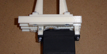
To drive it, I used a servo motor test board and a USB phone charger (2.5A) But you can also use and arduino.
Servo tester board:
More from this category
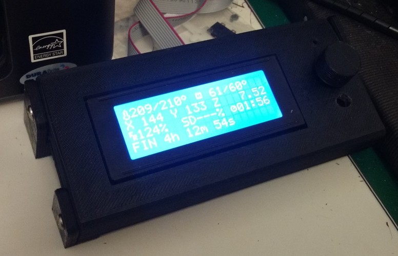
Smart LCD Case Stand Alone version
A stand alone LCD case for the RepRap Smart LCD with SdCard reader
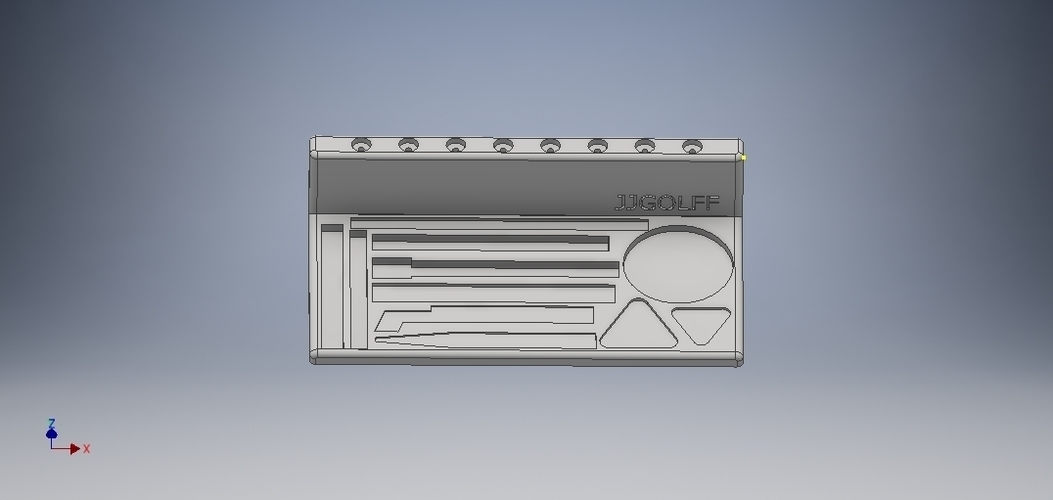
Mobile repair tools
by jjgolff
Herramientas de apoyo para la reparación de los móviles. Impresora 3d 220 x 220 x 220. PLA....
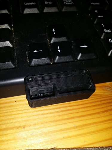
SD Card Flash Drive Holder
by Gpasteve
SD Card/ Flash drive holder that can be mounted to a 3d printer, a desk or a shelf .
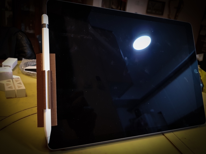
Apple Pencil with Smart Cover clips for iPad Pro
by vova_chmarak
Clips for iPad Pro with Smart Cover and apple pencil
Flexible covid ear saver (13 to 24 cm long)
by imakina
Flexible ear saver 13 to 23 cm long. Only 1 gram each piece.
Comments (11)
Sign in to leave a comment.
Hello sir I am student of engineering and I make project can you provide solidworks file ???
Hello and thank you for your interest. I do not use SolidWorks and this was done on Fusion360. I can upload the Fusion files if you like.
Hi, would it be possible to email me the part files because they are saving to my computer as if they had been sliced. my email is maria.peralta@du.edu. thank you so much and if that's not possible that is also ok.
Good design, Provides the best amount of force because there are not components to flex between the motor and the jaws.
Hi, thanks for excellent design. What is max/min distance between jaws?
Congrats.. excellent Job!
Looking really good. I would like to use your design for a different sized servo. Do you have some CAD-Files (.step would be great) for me to adapt the size?