
Description
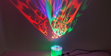
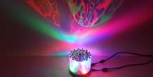
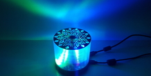
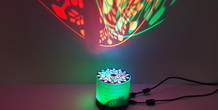
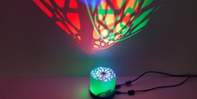
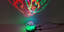
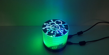
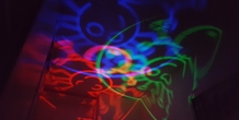
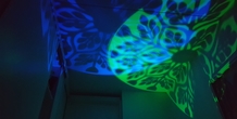
The idea is to project figures on to the sealing of your room. These projections are in Red, Green and Blue light. The round disk turns once in a while so the projections also move. To make more effects an Arduino also switches the LEDs on or off. I tried to make some videos and posted them on Facebook. Yes I know it’s not the best place for this and I should make a YouTube account for this. Also the videos are not edited in any way and just made with my smartphone. But you will get an idea how this RGB Lamp behaves :-) . But I have speeded it up in the Arduino just for the video.
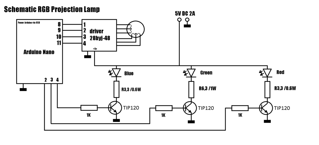
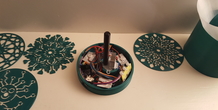
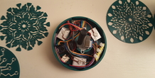
This RGB Projector Lamp has an RED LED, Green LED, and Blue LED, stepper driver, 28byj-48 stepper and an Arduino Nano. There are no screws or bolts needed. Everything just clicks together. (Also needed is a transistor like TIP20 and some resistors)
I also included an Arduino Script I use myself at the moment.
Please see pictures for a wiring diagram. The LEDs I used are 1W each. Each LED is thermo glued to a heat sink. The Arduino gets its power through the usb port
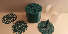
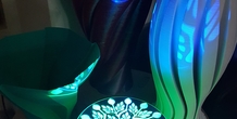
At the moment I have made 4 different disks. Also I included a blank one, so you can make your own.
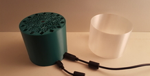
Printed in green PLA, 0,2mm resolution using a 0.4 mm nozzle. If you use the same resolution everything should find nicely. The mid (cylinder) part is printed using the “spiral outer contour mode “in Cura.
I also printed this mid part in translucent PET-G, but the reflections lose their sharpness using it.
Because I do not have a YouTube Account, but I still want to give you an idea how it works, I uploaded some videos on Facebook. I speeded up the Arduino sketch for this video. Normally it go’s way slower :-) Please see: https://www.facebook.com/100000611642601/videos/vb.100000611642601/1850079701689067/?type=3
https://www.facebook.com/100000611642601/videos/vb.100000611642601/1850078735022497/?type=3
https://www.facebook.com/100000611642601/videos/vb.100000611642601/1850077891689248/?type=3
https://www.facebook.com/100000611642601/videos/vb.100000611642601/1850076758356028/?type=3
If you think there is a better way of showing these videos please let me know :-).
If you think I forgot something, made a mistake or you have questions, feel free to ask or comment :-)
Arduino sketch:
//RGB Projector Lamp
#define IN1 8 //pins for stepper driver #define IN2 9 #define IN3 10 #define IN4 11
int RedLedPin = 2; //red led transistor base to pin 2 int GreenLedPin = 3; //green led transistor base to pin 3 int BlueLedPin = 4; //red led transistor base to pin 4
int Steps = 0; boolean Direction = true;// gre unsigned long last_time; unsigned long currentMillis ; int steps_left=4095; long time; void setup() { Serial.begin(115200); pinMode(IN1, OUTPUT); pinMode(IN2, OUTPUT); pinMode(IN3, OUTPUT); pinMode(IN4, OUTPUT);
pinMode(RedLedPin, OUTPUT); // Set pin for output to control transistor of red led pinMode(GreenLedPin, OUTPUT); // Set pin for output to control control transistor of green led pinMode(BlueLedPin, OUTPUT); // Set pin for output to control control transistor of blue led
} void loop() { while(steps_left>0){ currentMillis = micros(); if(currentMillis-last_time>=1000){ stepper(1); time=time+micros()-last_time; last_time=micros(); steps_left--; } } Serial.println(time); Serial.println("Wait :-)"); delay(100000); // change value stop time Direction=!Direction; steps_left=4095; }
void stepper(int xw){ for (int x=0;x<xw;x++){ switch(Steps){ case 0: digitalWrite(IN1, LOW); digitalWrite(IN2, LOW); digitalWrite(IN3, LOW); digitalWrite(IN4, HIGH); analogWrite(RedLedPin, 180); // By changing values from 0 to 255 you can switch the transistor analogWrite(GreenLedPin, 0); analogWrite(BlueLedPin, 0); break; case 1: digitalWrite(IN1, LOW); digitalWrite(IN2, LOW); digitalWrite(IN3, HIGH); digitalWrite(IN4, HIGH); analogWrite(RedLedPin, 180); // By changing values from 0 to 255 you can switch the transistor analogWrite(GreenLedPin, 180); analogWrite(BlueLedPin, 0); break; case 2: digitalWrite(IN1, LOW); digitalWrite(IN2, LOW); digitalWrite(IN3, HIGH); digitalWrite(IN4, LOW); analogWrite(RedLedPin, 0); // By changing values from 0 to 255 you can switch the transistor analogWrite(GreenLedPin, 180); analogWrite(BlueLedPin, 0); break; case 3: digitalWrite(IN1, LOW); digitalWrite(IN2, HIGH); digitalWrite(IN3, HIGH); digitalWrite(IN4, LOW);
analogWrite(RedLedPin, 0); // By changing values from 0 to 255 you can switch the transistor analogWrite(GreenLedPin, 180); analogWrite(BlueLedPin, 255); break; case 4: digitalWrite(IN1, LOW); digitalWrite(IN2, HIGH); digitalWrite(IN3, LOW); digitalWrite(IN4, LOW);
analogWrite(RedLedPin, 0); // By changing values from 0 to 255 you can switch the transistor analogWrite(GreenLedPin, 0); analogWrite(BlueLedPin, 255); break; case 5: digitalWrite(IN1, HIGH); digitalWrite(IN2, HIGH); digitalWrite(IN3, LOW); digitalWrite(IN4, LOW);
analogWrite(RedLedPin, 180); // By changing values from 0 to 255 you can switch the transistor analogWrite(GreenLedPin, 0); analogWrite(BlueLedPin, 255); break; case 6: digitalWrite(IN1, HIGH); digitalWrite(IN2, LOW); digitalWrite(IN3, LOW); digitalWrite(IN4, LOW);
analogWrite(RedLedPin, 0); // By changing values from 0 to 255 you can switch the transistor analogWrite(GreenLedPin, 180); analogWrite(BlueLedPin, 255); break; case 7: digitalWrite(IN1, HIGH); digitalWrite(IN2, LOW); digitalWrite(IN3, LOW); digitalWrite(IN4, HIGH); analogWrite(RedLedPin, 0); // By changing values from 0 to 255 you can switch the transistor analogWrite(GreenLedPin, 180); analogWrite(BlueLedPin, 255); break; default: digitalWrite(IN1, LOW); digitalWrite(IN2, LOW); digitalWrite(IN3, LOW); digitalWrite(IN4, LOW); analogWrite(RedLedPin, 180); // By changing values from 0 to 255 you can switch the transistor analogWrite(GreenLedPin, 180); analogWrite(BlueLedPin, 255); break; } SetDirection(); } } void SetDirection(){ if(Direction==1){ Steps++;} if(Direction==0){ Steps--; } if(Steps>12){Steps=0;} if(Steps<0){Steps=10; }
}
More from this category
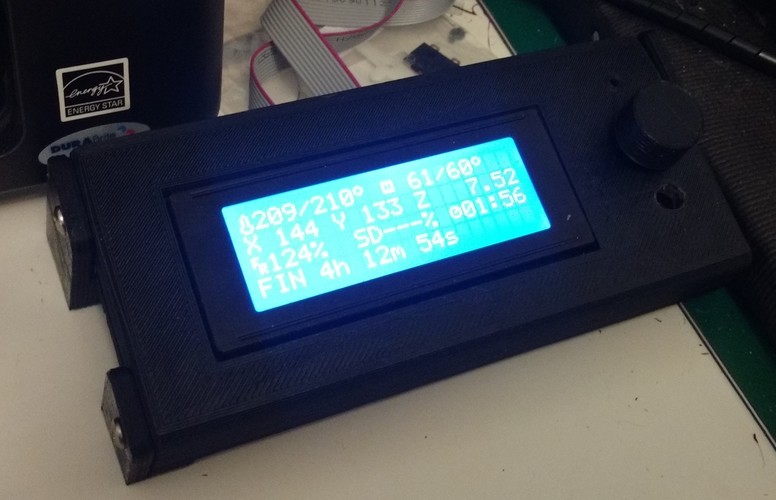
Smart LCD Case Stand Alone version
A stand alone LCD case for the RepRap Smart LCD with SdCard reader
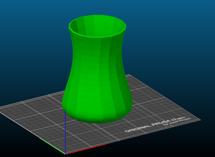
Simple Vase
by ANBR
This is my first design created by studying 3D modeling software. It is very simple, but we ...
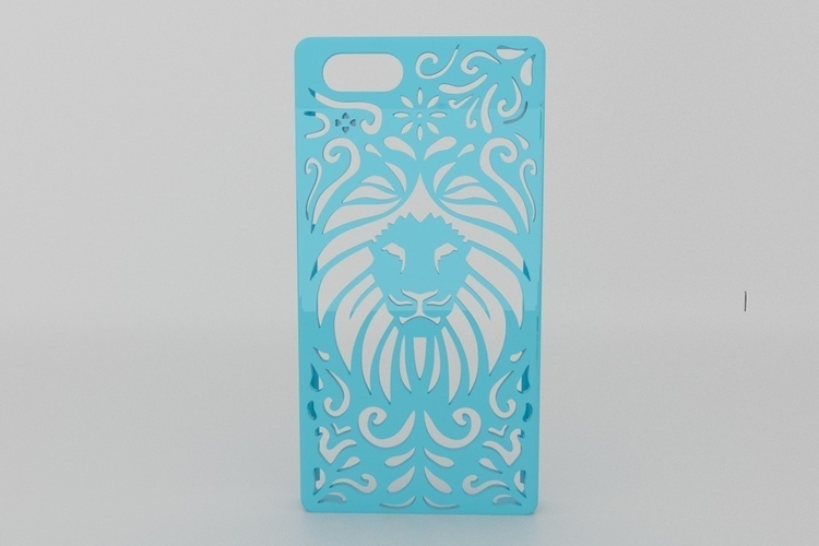
Lion Floral Iphone Case 6/6s
This beautiful Iphone case surely looks great and is easy to print. The design was inspired by a...
Comments (1)
Sign in to leave a comment.
No comments yet. Be the first to comment!