
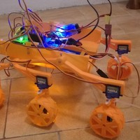


SummaryRC vehicle inspired by Mars rover Curiosity. Parts are printed on 3D printed. Main Processing Unit is Ardunio Mega. For moving used 6 9g servos with metal gear and edited for 360 rotating, for steering used 6 standart 9g servos.
Control is standard 4 channels. Power by 2S or 3S lipo battery - 6V SBEC.
------ Rover Mk II ----
https://www.youtube.com/watch?v=puso_W5l1AA
must see!
youtube:
0- presentation control https://www.youtube.com/watch?v=wAg5VBJ3dfA
1- https://www.youtube.com/watch?v=4kdi7T4iqAI
2 - https://www.youtube.com/watch?v=Wh_syhhbGSI
simple instruction: http://www.mochr.cz/index.php?id=rc-rover ( wait for complete...)
WARNING
new homepage:
http://www.mochr.cz/index.php?id=rc-rover InstructionsArduino files are in the RAR archive.
BOM
6x 9g servo (TG9e, TowerPro SG90)
6x 9g servo with metal gear (TGY-5009M)
Arduino Mega 2560
SBEC Lipo 5/6V 5/6A for 3S lipol
3S Li-pol about 1300mAh
12x servo extension cable (10-30cm)
12x resitor 2.2K ohm
universal PCB
green LED 3mm
red LED 3mm
yellow LED 3mm
3x resistor 160 Ohm
some pins
42x screw M2x6
6x screw M2.5x6
2x screw M3x25
8x screw M3x6
8x nut M3
4x nut M2
4x white LED 5mm
4x red LED 5mm
RC TX and RX
connector to Arduino
cable ties
3D printed parts
Arduino setup
After build Rover is needed to center the servos.
Upload this file to Arduino.
// 2 - 7 for all steering servos
// 8 - 13 for all wheels servos
int pin = 13;
check all servos with serial monitor for center position. My value is about 1300-1500. Value write to this file , and upload to Arduino.
// Data from calibration servos - center position of servo
int W1_center = 1350;
int W2_center = 1390;
int W3_center = 1360;
int W4_center = 1370;
int W5_center = 1435;
int W6_center = 1355;
int S1_center = 1500;
int S2_center = 1480;
int S3_center = 1420;
int S4_center = 1410;
int S5_center = 1480;
int S6_center = 1480;
Now you need center signal from RC. Connect RX to PCB and Arduino connect with PC. Control stick on TX set to neutral. Serial monitor write some values. Copy this values to Excel and make average value ( about 50 values is OK). Repeat to second channel.
// calibration RX signal
Serial.println( value_ch1);
and
// calibration RX signal
Serial.println( value_ch2);
Servo modifying
Servo with metal gear use to wheel. You must modifying to countinous rotating. Cut of potentiometer, add 2 resitors, cut of pin on tooth wheel.
instruction for example: https://learn.adafruit.com/modifying-servos-for-continuous-rotation/overview
Loading prints...
RC MARS Rover
4
likes
1
collection
Tags:
Creative Commons Attribution
You can distribute, remix, adapt, and build upon the material in any medium or format, as long as attribution is given to the creator.
 Licensed under CC BY


Loading comments...